
You’ve probably seen wave interference before in the context of water waves or other waves. In a region with multiple electromagnetic waves, as long as the material is linear (the permittivity and refractive index are independent of the strength of the electromagnetic field), the waves will add according to the principle of linear superposition. If two waves meet that are in phase (in step) with one another, they will interfere constructively, adding to produce a stronger total field. If two waves meet that are $latex 180^o$ out of phase with one another, they will interfere destructively, subtracting to cancel part or all of the field in that region. Of course, we can also have intermediate cases.
Most light sources (the sun, lightbulbs) produce incoherent light, which will be described in the next section. Interference is usually less obvious with incoherent light sources, and more difficult to observe in ordinary life, although not impossible. Laser light, on the other hand, has a high degree of coherence, making interference much easier to observe.
The classic experiment to demonstrate interference is the two-slit experiment. In this experiment, a light wave is passed through two slits, whose dimensions and separation are on the order of the wavelength of the light. In this way, the light wave is split into two light waves, and each of the new waves spreads out due to diffraction. This is diagrammed below.
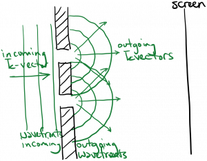
When the two new waves meet one another, they will interfere constructively in some places, and destructively in others. his can be observed in the following animation.
You’ve seen this phenomenon before – for example, when you drop two pebbles into a pond, and observe the water waves spreading out from each pebble and meeting to form a cross-hatch pattern.
Unlike water, we can’t see the light interfering at all the points where the light waves meet – we need something for the light to bounce off of to reach our eyes. So we can put a screen up some distance after the slits, and observe the light bouncing off of the screen to our eyes (effectively ‘sampling’ the intensity in that plane). What we will observe on the screen are bright and dark spots, corresponding to constructive and destructive interference of the two waves in the plane of the screen. This is shown in the next two animations, which show light traveling from the slits to different individual points on the screen. Also shown is the time-average light intensity on the screen.
As you can see in the animations, the type of interference (constructive or destructive) at a point on the screen is determined by the relative distance the light travels from each slit to that point. If the two waves arrive at a point in phase with each other, we will see constructive interference at that point.
We can treat all of this more mathematically. Below is a diagram of the two slit experiment, defining the coordinate axes and various dimensions.
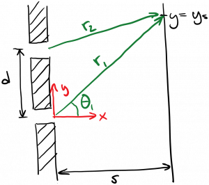
The waves exiting the slits are not plane waves (although they could be decomposed into a sum of plane waves). A reasonable approximation is to treat them as cylindrical waves. If we take the origin at the location of the bottom slit, we could write the wave leaving that slit as
$latex \displaystyle E_1 = A \cos{(k \rho – \omega t + \phi_1)} $
where $latex \rho$ is the cylindrical radius. (Power conservation says that this wave should decrease in amplitude as $latex 1 / \sqrt{\rho}$, but let’s not worry about that for the moment.) If we want to evaluate this wave at location $latex y = y_s$ on the screen, it will be
$latex \displaystyle E_1 = A \cos{(k r_1 – \omega t + \phi_1)} $
where $latex r_1 = \sqrt{s^2 + y_s^2}$ is the distance from the bottom slit to the chosen point on the screen. The wave originating at the top slit evaluated at the same point on the screen is
$latex \displaystyle E_2 = A \cos{(k r_2 – \omega t + \phi_2)} $
where $latex r_2 = \sqrt{s^2 + (y_s – d)^2}$ is the distance from the top slit to the chosen point on the screen. We’ve assumed that both waves have the same amplitude $latex A$. By linear superposition, the total wave is $latex E_{tot} = E_1 + E_2$. We’re going to use the identity
$latex \displaystyle \cos{\alpha} + \cos{\beta} = 2 \cos{\frac{\alpha + \beta}{2}} cos{\frac{\alpha – \beta}{2}} $
to obtain
$latex \displaystyle E_{tot} = 2 A \cos{\left( \frac{k (r_1 + r_2)}{2} – \omega t + \frac{\phi_1 + \phi_2}{2}\right) } \cos{\left( \frac{k (r_1 – r_2)}{2} + \frac{\phi_1 – \phi_2}{2}\right)} $
The intensity is proportional to the total field squared. As usual, we are most interested in the time-averaged intensity, which is the intensity integrated over many periods of oscillation and divided by the integration time:
$latex \displaystyle I_{avg} = \frac{C}{N T} \int_0^{NT} |E_{tot}|^2 dt $
where $latex C$ is the constant of proportionality, and $latex N$ is a large integer. The only time dependence in our $latex E_{tot}$ is the $latex \omega t$ within one of the cosines. Both cosines will be squared in the intensity equation above. Integrating $latex \cos^2 (\omega t + “blah”)$ over a period $latex T$ will yield $latex T/2$ for any time-independent “blah”. Therefore, our time average intensity becomes
$latex \displaystyle I_{avg} = 2 A^2 C \cos^2 {\left( \frac{k (r_1 – r_2)}{2} + \frac{\phi_1 – \phi_2}{2}\right)}$
$latex = A^2 C [ \cos{( k (r_1 – r_2) + (\phi_1 – \phi_2))} + 1] $
Let’s assume that the starting phase at each slit is the same, so that $latex \phi_1 – \phi_2 = 0$. In this case, the intensity will be maximum and we will observe a bright spot (fringe) at any location on the screen where
$latex k(r_1 – r_2) = 2 \pi m$
where $latex m$ is any integer. This is equivalent to saying that we obtain a bright spot at locations on the screen where the waves from the two slits are in phase with each other. Since $latex k = 2*pi / \lambda$, we can also write this as
$latex r_1 – r_2 = m \lambda$
This says that we obtain a bright spot at locations on the screen where the difference in distance from the two slits equals an integer number of wavelengths. Conversely, the intensity will be zero and we will observe a dark spot at any location on the screen where
$latex k(r_1 – r_2) = (2 m + 1) \pi $
or
$latex r_1 – r_2 = (2m + 1) \frac{ \lambda}{2}$
Check out this lovely video of two-slit experiment with incoherent (!) light and water waves:
You must be logged in to post a comment.