
An interferometer is a device designed to create and measure wave interference, usually as a way to indirectly measure another quantity of interest. For example, we may wish to ascertain the coherence length of a laser. This can be measured using a Michelson interferometer, diagrammed below:
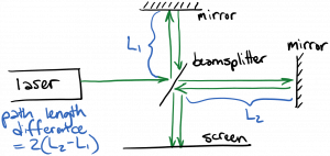
The incoming laser beam is split to travel along two paths by a beamsplitter, which is a device that partly reflects and partly transmits light (e.g. a slab of glass). Each wave reaches a mirror and is sent back so that the two waves are recombined and projected onto a screen. The path length traveled by each wave can be varied by moving the mirrors. Of course, what’s important is the relative path length: the difference in the two path lengths. As we’ve seen, if the difference in path lengths equals an integer multiple of a wavelength, the two waves will interfere constructively at the center of the beam, leading to a bright spot on the screen. (There will be dark spots adjacent to the bright spot, owing to parts of the beam traveling at off angles.) This is nicely illustrated in the following animation:
https://www.youtube.com/watch?v=UA1qG7Fjc2A
There’s another consideration, however. If the difference in path length of the two paths is greater than the coherence length of the source, there will be a random phase difference between the two waves, and the bright and dark spots will be smeared out so that we observe more uniform intensity on the screen. Therefore, to measure the coherence length, we can steadily move one mirror back until the clear bright and dark spots (fringes) are no longer visible; at that point, the path difference must exceed the coherence length, allowing us to estimate the coherence length of the light source.
Another interferometer of great importance for laser analysis is the Fabry-Perot interferometer, which consists of two mirrors facing one another, as shown below:
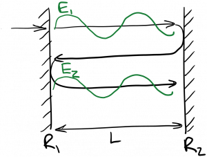
If light is coupled into the Fabry-Perot interferometer (perhaps through one of the mirrors, if it allows some transmission), the light will bounce back and forth between the mirrors repeatedly. (You may recall that many lasers use this same configuration of mirrors.) The light will interfere with itself, as shown on the diagram. The total light traveling to the right consists of light newly coupled into the interferometer, plus light that has undergone one round trip, plus light that has undergone two round trips, etc. Whether these waves interfere constructively or destructively depends on the round-trip distance between the mirrors: if it is an integer multiple of a wavelength, the interference will be constructive. Since the round trip distance is given by $latex 2 L$, for constructive interference we need
$latex \displaystyle 2 L = m \lambda$
Let’s analyze this in more detail. Take the direction normal to the mirrors to be the $latex z$ direction, with $latex z = 0$ corresponding to the left mirror $latex R_1$. I’ll write $latex E_1$ on the diagram above in phasor form as
$latex \displaystyle E_1 = A e^{i k z}$
The next wave propagating to the right, labeled $latex E_2$, is $latex E_1$ after it has undergone a full round trip in the cavity. What happens to $latex E_1$ on a round trip? Well, it propagates the length of the cavity $latex L$, which means it picks up phase $latex k L$; then it reflects from mirror $latex R_2$; then it propagates the length of the cavity $latex L$ again, picking up another $latex k L$ in phase; and finally it reflects from mirror $latex R_1$. We can write this mathematically as
$latex \displaystyle E_2 = R_1 e^{i k L} R_2 e^{i k L} E_1$
$latex \displaystyle = R_1 R_2 e^{2 i k L} E_1$
Let’s assume $latex R_1 = R_2 = R$ for simplicity. We’re going to try to sum up all of the waves propagating to the right, so that we can have the total rightward-propagating wave. This would be
$latex \displaystyle E_{tot} = E_1 + E_2 + E_3 + …$
$latex \displaystyle = E_1 [1 + R^2 e^{2 i k L} + R^4 e^{4 i k L} + … ]$
The series in brackets is a geometric series, which converges if $latex |R^2 e^{2 i k L}| < 1$. The result is
$latex \displaystyle E_{tot} = \frac{E_1}{1 – R^2 e^{2 i k L}} $
If we take $latex A = 1$, we can plot the intensity vs. normalized mirror separation $latex L / \lambda$ at $latex z = 0$ and $latex t = 0$ for various values of mirror reflectivity $latex R$:
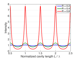
You can clearly see the resonances that occur due to constructive interference every time $latex 2 L$ is an integer multiple of $latex \lambda$. These resonances increase in intensity as the mirror reflectivity increases, because each subsequent ‘bounce’ has a larger amplitude, and the constructive interference is stronger. At the same time, the ‘troughs’ in-between the resonances deepen as $latex R$ increases, because the destructive interference is also getting stronger.
If we couple light into this Fabry-Perot resonator externally, what will we observe? If the reflectivity of each mirror is high, the resonator will act like a filter. Light whose wavelength aligns with a resonance (wavelengths which satisfy $latex 2 L = m \lambda$) can couple strongly into the cavity between the mirrors, and some of that light will transmitted to the other side of the cavity. If, on the other hand, the mirror separation equals an odd multiple of a quarter wavelength (corresponding to the troughs between resonances) light will not be able to couple into the cavity effectively, and almost all of it will be reflected out. The overall transmission of the interferometer is therefore proportional to the plot of intensity inside the cavity, above. The Fabry-Perot resonator acts like a comb filter, passing certain wavelengths while rejecting others, depending on the mirror separation.
What does the light look like inside the cavity formed by the two mirrors? For large values of $latex R$, the waves propagating left and right have nearly equal amplitudes, creating a standing wave. For example, here’s an animation for $latex L = 3 \lambda$ and $latex R = = -0.9$, showing forward, backward, and total (forward + backward) waves:
You can see the total field is almost entirely standing, resembling a jumprope or wire vibrating when pinned at either end. If we reduce the cavity length (mirror separation) $latex L$ to be $latex 2.75 \lambda$, the multiple bounces within the cavity destructively interfere with one another, so that all of the waves inside the cavity are very small:
Let’s go back to $latex L = 3 \lambda$ and reduce the magnitude of the reflection coefficient at the mirrors, so that $latex R = -0.6$:
In this case, we have constructive interference, but both the forward and backward waves are reduced. Remember that the forward wave is the sum of the first forward wave coupled into the cavity, plus that forward wave after one round trip, plus that forward wave after two round trips, etc. Even though all of the forward waves after multiple round trips are constructively interfering, each forward wave has a substantially reduced amplitude compared to the forward wave on the previous round trip, because $latex |R|$ is smaller. Therefore, the sum of the forward waves is smaller. Put another way, more light is leaking out on each bounce. The total field is a mix of standing and traveling waves, as the backward wave is significantly weaker than the forward wave. We can push this trend further by setting $latex R = -0.3$:
Now the forward wave is weaker, and the backward wave is nearly zero. so that the total field is almost equal to the forward wave, and consists almost entirely of a (forward) traveling wave.
*Write out standing-wave fields (do sum)
In addition to its use as an interferometer, we can see why Fabry-Perot cavities are useful for many lasers. For one thing, it provides positive feedback, as we’ve discussed. For another, with high mirror reflectivities it can greatly strengthen the fields inside the cavity, which is desirable to enhance the stimulated emission rate, as we’ll see later. Finally, it selectively enhances the fields oscillating at certain wavelengths, which is often desirable.
You must be logged in to post a comment.