
Most semiconductor lasers can be broadly classified into two basic structures: edge-emitting lasers, or surface-emitting lasers. Let’s take a look at the structure of each.
A typical edge-emitting laser will have the longitudinal direction of the optical cavity oriented perpendicular to the direction of electrical current flow in the diode. A typical structure is diagrammed below.
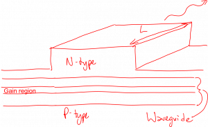
This is a ridge-waveguide separate confinement heterostructure, and there’s a lot going on in the design of this device, but let’s start with the basics. Current flows from the p-side to the n-side, vertically. Typically there will be an electrical contact on top and an electrical contact on the bottom (not shown). The axis of the optical cavity is ‘into the screen’ and is labeled with $latex L$. The front and back faces of the structure are typically just cleaved crystal facets, so the transition from semiconductor to air provides the reflectivity of those mirrors. This reflectivity is typically fairly low; for example $latex R = (3.6 -1) / (3.6 + 1) = 0.57$. Therefore, the cavity length $latex L$ must be fairly long in order to have a reasonably low value of the threshold current, typically $latex L \equiv 100 \mu m$. The vertical dimensions of the structure are much smaller than this.
The slightly more complicated aspects of this structure are the ridge and the waveguide. The waveguide is formed by using a semiconductor material with a higher refractive index compared to the outermost semiconductor materials. This is done to guide the optical mode in the vertical direction. Similarly, the ridge visible on top of the structure is fabricated in order to guide the optical mode in the horizontal direction. Combined with the front and back faces, the optical mode is confined in all three dimensions.
A nicer diagram of an edge-emitting laser structure can be found here:
https://www.photonics.com/EDU/Handbook.aspx?AID=25099
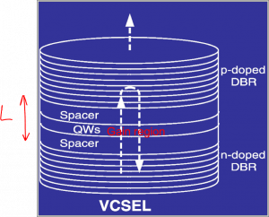
A vertical-cavity surface-emitting laser (VCSEL) is diagrammed below. In this structure, the current flow and the optical axis are parallel to one another, and both are oriented vertically. The optical cavity (mirror separation) is typically short, on the order of a wavelength of the light, and the effective length of the gain region is even shorter than that, as it is typically composed of very thin layers that the light is traveling perpendicular to. Therefore, the mirrors must have very high reflectivity in order to maintain a reasonably low threshold current. We can’t use metal for these mirrors, because metal has unacceptably high optical absorption for this purpose, and would short out the doped regions. Therefore, we use distributed Bragg reflector (DBR) mirrors, which are stacks of periodically repeating quarter-wavelength-thick layers with alternating high and low refractive indecies. Due to constructive interference between reflected waves from the many interfaces, DBRs can exhibit extremely high reflectivities (> 0.99) over limited wavelength ranges.
VCSELs are typically only used for low-power applications such as short-distance communications. They offer several advantages when compared to edge-emitting lasers:
- shorter cavity length means its easier to achieve single-mode operation
- output beam has a more circular cross section due to greater symmetry of the ‘waveguide’
- vertical output makes it easier to integrate with other electronics
Nicer VCSEL diagrams can be found online, such as:
https://www.photonics.com/EDU/Handbook.aspx?AID=25102
However, edge emitting lasers are still preferable for long-haul fiber communications applications, due to the higher powers and sharper linewidths typically desired.
You must be logged in to post a comment.